Difference between revisions of "10.525GHz Doppler Effect Microwave Motion Sensor SKU: CQRSENWB01"
(→Signal Detection Range) |
(→Working Principle) |
||
| Line 69: | Line 69: | ||
=='''Working Principle'''== | =='''Working Principle'''== | ||
The following diagram demonstrates the working principle of the sensor module. It works by amplifying a tiny signal which is received by the microwave sensor, and then through the comparison circuit it converts the signal into a square signal with a digital output of 0 or 1 which an Arduino or other micro controller can easily handle. | The following diagram demonstrates the working principle of the sensor module. It works by amplifying a tiny signal which is received by the microwave sensor, and then through the comparison circuit it converts the signal into a square signal with a digital output of 0 or 1 which an Arduino or other micro controller can easily handle. | ||
| − | [[image:10.525GHz Doppler Microwave Sensor- | + | [[image:10.525GHz Doppler Microwave Sensor-10.jpg|thumb|1000px| center]] |
---- | ---- | ||
Revision as of 13:02, 17 June 2021
Contents
Description
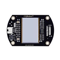
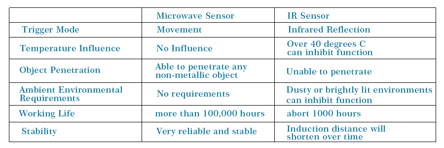
The microwave motion sensor is a microwave moving object detector which is designed according to the principle of Doppler Radar. This differs from the method used by a regular infrared (IR) sensor as microwave is sensitive to a variety of objects that are microwave-reflective, and its sensor readings are not affected by the ambient temperature.
Comparison with IR Sensor:
It is widely used not only in the detection of human body, but also many other objects. With the character of long detection distance and high sensitivity, it works without the limitation of ambient temperature and has come widely used in industrial, transportation and civil applications such as measuring speed, liquid levels, automatic door motion detection, automatic washing, production line material detection and car reversing sensors etc.
The detection objects of the microwave sensor are universal. When it comes to the actual use in life, we will usually match it with another sensor for targeted detection. For example, a combination of microwave sensor and infrared pyroelectric sensor. It can accurately judge whether someone is passing by without being disturbed by sunlight and clothing color, and will not react to other objects.
Attention
There is an ultra-high frequency MOS device inside the microwave motion sensor. When you are testing, please use battery power as much as possible to avoid breakdown that is caused by the static voltage difference between the power supply and the test equipment, such as an oscilloscope.
In addition, we suggest that you use battery power to ensure the best detection effect when you are operating the product.
Features
- Non-contact detection.
- Suitable for harsh environments because : will not be influenced by temperature, humidity, noise, airflow, dust, and the lights.
- Strong resistance to radio frequency interference.
- Low output power, no harm to human bodies.
- Long range of detection.
- Allow detection for non-living objects.
- Microwave has perfect directivity, the speed is same as the speed of light.
- Comes with development resources and manual (examples for Raspberry Pi/Arduino)
Pin Description and Size
Connection Diagram
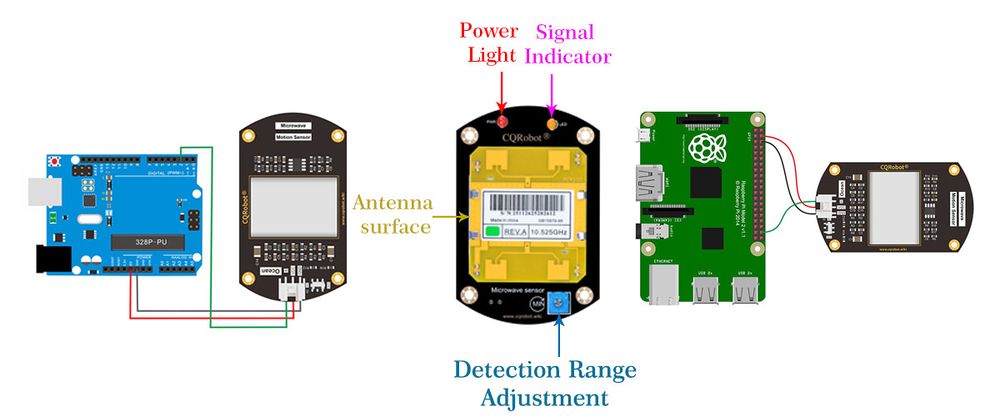
NOTE: Align the antenna surface towards the area you need to detect.
NOTE: The sensor can be adjusted continuously within the range of 2-16m. Turn the potentiometer in the direction of MIN and the detection range decreases. Turn the potentiometer in the opposite direction and the detection range increases.
Specifications
- Working Pressure : 5V Plus/Minus 0.25V
- Working Current (CW): 60mA max., 37mA typical
- Dimension: 76.7mm * 50mm
- Mounting hole size: 3.0mm
Emission Parameter
- Detection Range: 2m to 16m continuously adjustable (min: 2m, max: 16m)
- Emission Frequency: 10.525 GHz
- Frequency Accuracy: 3MHz
- Output Rate (Min): 13dBm EIRP
- Harmonic Emission: Less Than -10dBm
- Average Current (5% DC): 2mA typ.
- Pulse Width (Min): 5uSec
- Load Cycle (Min): 1%
Receiver Parameter
- Sensitivity(10dB S/N ratio) 3Hz-80Hz Broadband: -86dBm; 3Hz-80Hz Bandwidth Clutter: 10uV.
- Antenna Gain: 8dBi
- Vertical Level: 3dB Beam-width: 36 degrees
- Horizontal Level: 3dB Beam-width: 72 degrees
Ocean Wire Specifications
- Cable Specifications: 22AWG
- Material: Silicone
- Withstand Voltage: Less Than 50V
- Withstand Current: Less Than 1000MA
- Length: 21cm
- Line Sequence: Red-Power Supply Positive, Black-Power Supply Negative, Green-Control Board Signal Terminal.
Working Principle
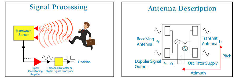
The following diagram demonstrates the working principle of the sensor module. It works by amplifying a tiny signal which is received by the microwave sensor, and then through the comparison circuit it converts the signal into a square signal with a digital output of 0 or 1 which an Arduino or other micro controller can easily handle.
Signal Detection Range
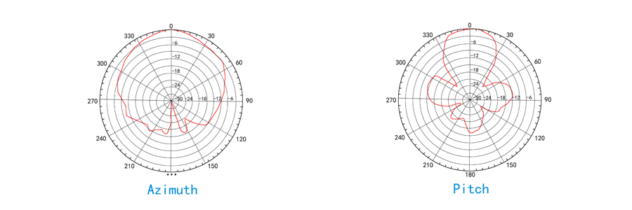
Detection Angle: The angle of detection is 72 degrees with the antenna in a parallel direction (azimuth) The vertical (pitch) direction of the antenna is 36 degrees.
Install
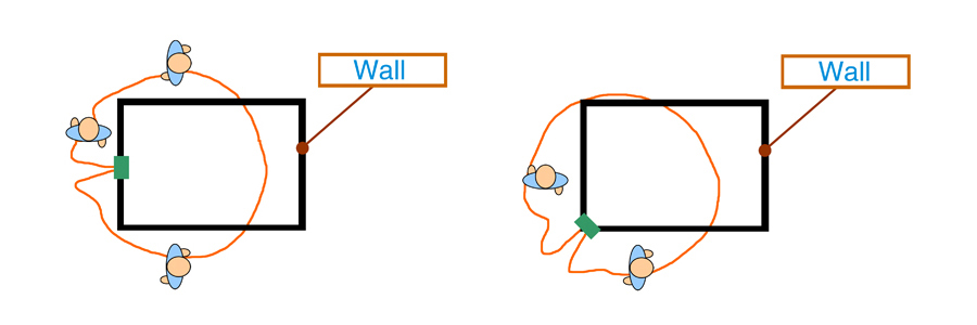
Microwaves can penetrate through walls. So sometimes it has inaccuracies when microwaves penetrate through outside walls and detect moving objects in non-target areas. Be sure to choose an installation location to avoid this!
Demo Code for Arduino
(1) Experiment Information: we have use the Arduino Uno Development Board and Microwave Motion Sensor in the experiment to detect the moving range of people.
(2) Experiment Supply List:
① Arduino Uno Development Board --1
② Microwave Motion Sensor Model -- 1
③ 3PIN Digital Signal Line -- 1
(3) Wiring Diagram
ATTENTION: Put MsTimer2 File in \Arduino\libraries in compiler install content BEFORE BURNPROCESS.
Example:C:\Program Files\Arduino\libraries
#include <MsTimer2.h> //Timer interrupt function
int pbIn = 0; // Define the interrupt PIN is 0, that is, digital pins 2
int ledOut = 13;
int count=0;
volatile int state = LOW; //Define ledOut, default is off

void setup()
{
     Serial.begin(9600);
     pinMode(ledOut, OUTPUT);
     attachInterrupt(pbIn, stateChange, FALLING);
// Sets the interrupt function, falling edge triggered interrupts.
     MsTimer2::set(1000,process); // Set the timer interrupt time 1000ms
     MsTimer2::start();//Timer interrupt start
}

void loop()
{
    Serial.println(count); // Printing times of 1000ms suspension
    delay(1);
if(state == HIGH)
//When moving objects are detected later, 2s shut down automatically after //the ledout light is convenient.
  {
    delay(2000);
    state = LOW;
    digitalWrite(ledOut, state); //Turn off led
  }

 }

void stateChange()  //Interrupt function
{
  count++;

}

void process()   //Timer handler
{
  if(count>1)
//1000ms interrupt number greater than 1 is considered detected a moving object //(this value can be adjusted according to the actual situation, equivalent to //adjust the detection threshold of the speed of a moving object)
       {
                   state = HIGH;
                   digitalWrite(ledOut, state);    //Lighting led
                   count=0;   //Count zero
       }
        else
            count=0;
//In 1000ms, interrupts does not reach set threshold value is considered not detect //moving objects, interrupt the count number is cleared to zero.
}
On Arduino Board, upload the testing code with Arduino IDE software, connecting the wires and power up. First turn the 3V/5V switch to position 5V, after connecting to the UNO board, PWR(red) Led will be on. When detecting any human activity, the orange LED light will blink, D13 on UNO board will be blinking as well. At this time turn the switch to 3V, it will be as the same voltage as 5V. Lastly, adjust the potentiometer on the back, clockwise to decrease the sensitivity, otherwise enlarge the sensitivity.
Demo code for Raspberry Pi
(1) Experiment Information: we use Raspberry Pi development board and Microwave Motion Sensor to detect human activities in certain ranges. The input function from Raspberry Pi’s GPIO is necessary for this experiment (please see http://wiringpi.com/download-and-install/ for instruction).
(2) Experiment Supply List:
① Raspberry Pi Development Board --1
② Microwave Motion Sensor Model -- 1
③ 3PIN Digital Signal Line -- 1
(3) Wiring Diagram
Attention: please make the wire facing toward the area that needed to be detected. Notice: The sensor is adjustable from range 2m-16m, the detecting ranging decrease as turning the potentiometer clockwise, the detecting range extend as potentiometer turning counterclockwise.
(4) Experiment Code:
#include <wiringPi.h>
#include <stdio.h>
int main()
{
  wiringPiSetup();
  char val;
  {
    pinMode(28,INPUT);//microwave motion sensor connecting to PIN28 on raspberry pi
  }

  while(1)//if someone passes by
  {
   val=digitalRead(28);
   if(val==0)
  {
   printf("Somebody is in this area!\n");
   delay(10);//delay10MS

  }
 Else//nobody passes by
  {
   printf("No one!\n");
   delay(10); //delay 10MS
 }}}
The programming part is implemented by C language ON. Raspberry Pi makes Microwave Motion Sensor work easier. PIR will make an output of data pin to a low level voltage if it detects a moving objects (Somebody is in this area); if no body was there, it is an output ( no one).
