Difference between revisions of "ITR9608-Photo Sensor"
| (One intermediate revision by the same user not shown) | |||
| Line 39: | Line 39: | ||
*Wire Sequence: Black-negative power supply, Red-positive power supply, Green-signal | *Wire Sequence: Black-negative power supply, Red-positive power supply, Green-signal | ||
---- | ---- | ||
| + | |||
| + | =='''Demo for Arduino'''== | ||
| + | |||
| + | <pre> | ||
| + | int Led = 13 ; | ||
| + | int buttonpin = 3; | ||
| + | int val ; | ||
| + | void setup () { | ||
| + | pinMode (Led, OUTPUT) ; | ||
| + | pinMode (buttonpin, INPUT) ; | ||
| + | Serial.begin(9600); | ||
| + | } | ||
| + | void loop () { | ||
| + | val = digitalRead (buttonpin) ; | ||
| + | Serial.println(val); | ||
| + | if (val == LOW) { | ||
| + | digitalWrite (Led, HIGH); | ||
| + | } else { | ||
| + | digitalWrite (Led, LOW); | ||
| + | } | ||
| + | } | ||
| + | </pre> | ||
| + | '''Test Methods and Results''' | ||
| + | |||
| + | 1. Upload the test code on the UNO R3 control board with Arduino IDE software. | ||
| + | |||
| + | 2. Connect the cable according to the wiring method and power on by USB cable. | ||
| + | |||
| + | 3. Turn on the serial monitor, and set the baud rate to 9600. | ||
| + | |||
| + | 4. When an object is sensed by the sensor groove, the D13 indicator on the UNO R3 control board is on, so is the DAT LED on the sensor, and output "0" on the serial monitor display (as shown in the picture below); Otherwise, the D13 indicator and the DAT LED are off, and output "1"on the display. | ||
| + | |||
| + | |||
| + | ---- | ||
| + | =='''Demo for Raspberry Pi'''== | ||
| + | <pre> | ||
| + | #include <wiringPi.h> | ||
| + | #include <stdio.h> | ||
| + | int main() { | ||
| + | wiringPiSetup(); | ||
| + | char val; { | ||
| + | pinMode(1,INPUT); | ||
| + | } | ||
| + | while(1) { | ||
| + | val=digitalRead(1); | ||
| + | printf("OUT:%d\n",val); | ||
| + | delay(100); | ||
| + | } | ||
| + | } | ||
| + | </pre> | ||
| + | '''Test Methods and Results''' | ||
| + | |||
| + | 1. Save the test code as a folder in the Raspberry Pi system. | ||
| + | |||
| + | 2. Execute the following commands in the terminal to run the program. | ||
| + | |||
| + | 3. When an object is sensed by the sensor groove, the terminal outputs "OUT: 0", and DAT LED on the sensor is on; Otherwise, it outputs "OUT: 1", and the DAT LED is off. | ||
| + | <pre> | ||
| + | cd TS1692 | ||
| + | ls | ||
| + | gcc TS1692.c -o TS1692 -lwiringPi | ||
| + | ls | ||
| + | sudo ./TS1690 | ||
| + | </pre> | ||
Revision as of 10:18, 30 July 2020
Contents
[hide]Introduction
The ITR9608 (Slot Optical Switch) is a gallium arsenide infrared emitting diode which is coupled with a silicon photo transistor in a plastic housing. The packaging system is designed to opt imizes the mechanical resolution, coupling efficiency, and insulates ambient light. The slot in the housing a provides a means of inte rrupting the signal with printer, scanner, copier, or other opaque material, switching the output from an”ON" to”OFF"state.
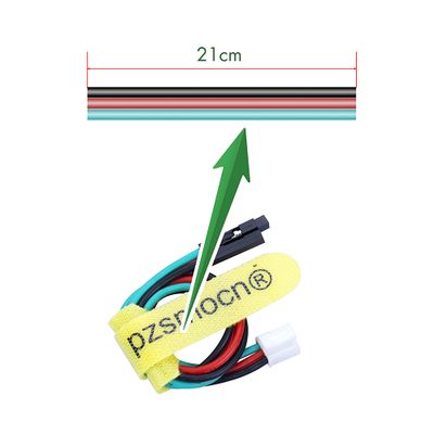
It's the photo interrupter sensor, also called smart car speed measuring module. The sensor comes with a JST PA SMT 3-Pin horizontal sticker and a buckle socket. Also, a JST PA 3-Pin to DuPont female single-head wire is offered to facilitate wiring. Length: 210mm, buckle attached.
Applications
- Copier
- Printer
- Facsimile
- Ticket vending machine
- Opto-electronic switch
- Motor speed detection
- Pulse counter
Product Size
Connection Diagram
Specifications
Sensor
- Operating Voltage: DC 3.3V-5V
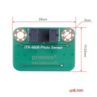
- Dimensions: 28mm * 35mm * 8.4mm
- Fixing Hole Size: 3mm
Wire
- Withstand Voltage: <50V
- Withstand Current: <1000MA
- Length: 21CM
- Wire Sequence: Black-negative power supply, Red-positive power supply, Green-signal
Demo for Arduino
int Led = 13 ;
int buttonpin = 3;
int val ;
void setup () {
	pinMode (Led, OUTPUT) ;
	pinMode (buttonpin, INPUT) ;
	Serial.begin(9600);
}
void loop () {
	val = digitalRead (buttonpin) ;
	Serial.println(val);
	if (val == LOW) {
		digitalWrite (Led, HIGH);
	} else {
		digitalWrite (Led, LOW);
	}
}
Test Methods and Results
1. Upload the test code on the UNO R3 control board with Arduino IDE software.
2. Connect the cable according to the wiring method and power on by USB cable.
3. Turn on the serial monitor, and set the baud rate to 9600.
4. When an object is sensed by the sensor groove, the D13 indicator on the UNO R3 control board is on, so is the DAT LED on the sensor, and output "0" on the serial monitor display (as shown in the picture below); Otherwise, the D13 indicator and the DAT LED are off, and output "1"on the display.
Demo for Raspberry Pi
#include <wiringPi.h>
#include <stdio.h>
int main() {
	wiringPiSetup();
	char val; {
		pinMode(1,INPUT);
	}
	while(1) {
		val=digitalRead(1);
		printf("OUT:%d\n",val);
		delay(100);
	}
}
Test Methods and Results
1. Save the test code as a folder in the Raspberry Pi system.
2. Execute the following commands in the terminal to run the program.
3. When an object is sensed by the sensor groove, the terminal outputs "OUT: 0", and DAT LED on the sensor is on; Otherwise, it outputs "OUT: 1", and the DAT LED is off.
cd TS1692
ls
gcc TS1692.c -o TS1692 -lwiringPi
ls
sudo ./TS1690


